









Short answer: E112B documents up to 960W AC charging input and a separate 10.5–60V DC/solar input up to 600W. These are ceilings, not assured constant rates, not permission to combine both paths, and not an exact recharge-time promise.
Use CEILING-SOURCE-CURVE-MEASURE: preserve the maximum as a boundary, identify the actual source, expect the observed rate to change, and measure the complete session you care about.
What the two input figures do—and do not—mean
| Documented field | Useful meaning | Unsupported conclusion |
|---|---|---|
| AC charging input: 960W max | Upper boundary for the documented AC charging path | 960W at every moment or a fixed full-charge time |
| DC/solar input: 10.5–60V, 600W max | Voltage window and upper boundary for the documented DC path | Every 600W-labelled panel produces 600W into the station |
| 1008Wh nominal battery energy | Nominal stored-energy specification | Exact wall energy, charging efficiency or a simple 1008÷960 time result |
| Separate AC and DC limits | Evaluate each path against its own instructions | 960+600=1560W combined input or automatic simultaneous permission |
Product check: review the current E112B product details, then compare the delivered regional label and manual before choosing a source.
Why the real input can be lower
A maximum is the top of an allowed or designed range, not a promise that the system will remain there. The charging source may offer less power, the battery-management system may reduce current as state of charge or temperature changes, and cable or controller limits may become the active boundary. Texas Instruments describes constant-current and constant-voltage stages as a general lithium-ion charging pattern; that explains why a curve can change, but it is not a test or controller description for E112B.
For solar charging, the JRC PVGIS manual shows why sunlight, module temperature, orientation, location and system conditions matter. A panel nameplate is therefore not a direct prediction of station input. The full source voltage must stay inside the documented E112B DC range, and the delivered instructions must approve the connector path.
Three concrete charging-session examples
- Low-state AC session: the display initially reports less than 960W. That can still be normal because 960W is a ceiling. Record source conditions and the full curve instead of diagnosing a fault from one moment.
- Variable-sun DC session: a compatible solar source remains inside 10.5–60V, but clouds, angle and temperature change the observed input. The 600W field caps the documented path; it does not assure an outdoor yield.
- Later high-state session: input falls as the battery approaches the selected end state. Generic staged-charging behaviour can explain tapering, but only the E112B display or an appropriate meter can document the actual session.
Measure a useful charging session
- Verify the delivered E112B label, charger, manual and regional outlet requirements.
- Choose one charging path and document the source, connector, voltage range and cable arrangement.
- Record starting state of charge, time, ambient conditions and whether the station is powering any load.
- Observe displayed input and warnings across the session rather than recording only the highest moment.
- Record the ending state, elapsed time and interruptions. Repeat only with the same boundary when making a comparison.
When the specification is useful
- You need to screen an AC source against the documented 960W maximum path.
- You need to screen a DC or solar source for the 10.5–60V window and 600W maximum.
- You are comparing measured sessions with the same start/end states and similar conditions.
When it is not enough
- You need an exact recharge time, efficiency or electricity-cost claim without a complete measurement.
- You want to add AC and DC maximums or assume simultaneous operation.
- The panel open-circuit voltage, connector, polarity, cable rating or current limit is missing.
- The setup uses damaged, coiled, daisy-chained or unsuitable mains leads.
Frequently asked questions
Does 960W AC input mean E112B always charges at 960W?
No. It is a documented maximum, not a constant-rate promise. Source conditions, charge state, temperature and battery-management decisions can change the observed input.
Can I add 960W AC and 600W DC to claim 1560W charging?
No. The authoritative record provides separate AC and DC maximums but does not establish simultaneous operation or an additive combined-input rating.
Does a 600W solar array ensure 600W into E112B?
No. The source must stay within the documented 10.5–60V DC range, and real input depends on irradiance, temperature, orientation, shading, wiring and controller behaviour.
Can I calculate exact recharge time from 1008Wh and 960W?
No. Dividing nominal Wh by a maximum input ignores losses, tapering, starting state, conditions and control behaviour. Measure the complete session with the delivered equipment.
What should I record during a charge test?
Record the charging source, start and end state of charge, elapsed time, displayed input, room or outdoor conditions, cable arrangement, warnings and any interruptions.
For an exact source question: ask FlashFish Europe about your charging source, then have a qualified reviewer confirm the delivered equipment.
Sources and evidence limits
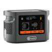
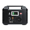
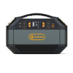
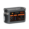
Checked 13 October 2026. E112B values come from the authoritative local product record and current Europe page. JRC PVGIS supplies solar-variability context, Texas Instruments supplies a generic staged-charging explanation and Electrical Safety First supplies general lead boundaries. FlashFish publishes this guide. No E112B AC, DC, solar, combined-input, efficiency or recharge-time session was tested for the article; the image is product context rather than a charging trace.




Zostaw komentarz
Ta strona jest chroniona przez hCaptcha i obowiązują na niej Polityka prywatności i Warunki korzystania z usługi serwisu hCaptcha.