

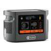
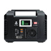

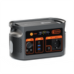







Short answer: sometimes one portable power station can run the original AC charger of another, provided the exact regional voltage, frequency, charger demand and manufacturer instructions all agree. This transfers energy; it does not combine the batteries into one larger pack. Conversion losses mean less energy arrives than leaves the donor.
The safest way to reason about the question is to separate three very different ideas: powering a recipient's normal charger, using a manufacturer-designed expansion-battery system, and electrically joining two independent outputs. Only the first is examined as a generic label check here. The second is model-specific. The third is not supported.
In this guide: TRANSFER method · connection paths · E106B/E103 screen · mistakes · FAQ
Use the TRANSFER method
T — Type of link: identify whether the proposal uses the recipient's original AC charger, a documented DC input, or a proprietary expansion port. Do not treat these as interchangeable.
R — Rated donor output: record the donor's delivered regional voltage, frequency, continuous watts, outlet limit and any simultaneous loads. A charger may be small, but its input still belongs inside the donor's complete load budget.
A — Accepted recipient input: read the recipient charger and station manual. Record the charger's input range and the station's stated charge-input ceiling. Use the original or expressly approved charger.
N — Never parallel independent outputs: do not connect two AC outlets together, backfeed a household circuit or improvise a Y-cable. A true parallel or expansion system needs a manufacturer-designed communication, protection and connection method.
S — Simultaneous-load budget: count everything the donor is running while it supplies the charger. Count everything the recipient is powering while it charges. Pass-through operation, where available, can introduce model-specific limits and heat.
F — Full conversion path: an AC transfer usually changes donor battery DC to AC, then the recipient charger changes AC back to DC. Both conversion stages and both stations consume energy.
E — Energy reserve: decide why the energy needs to move. Preserve donor energy for higher-priority loads and stop before the transfer undermines the original backup plan.
R — Review and stop: stop when voltage, frequency, polarity, connector, charger identity or manufacturer permission is unclear. A connector that fits is not evidence that the electrical path is correct.
| Question | Evidence needed | Stop condition |
|---|---|---|
| Can the donor run the charger? | Donor AC label plus charger's AC input label | Regional voltage/frequency mismatch or insufficient continuous headroom |
| Can the recipient accept the path? | Recipient manual and original charger | Unsupported charger, input or pass-through mode |
| Is a direct DC path allowed? | Exact voltage, current, polarity, protocol, connector and explicit instructions | Any missing field or an improvised adapter |
| Will the plan preserve useful energy? | Measured donor draw and recipient energy gain | The transfer consumes the reserve needed elsewhere |
Three connection paths are not equivalent
Recipient's original AC charger
This is the most understandable occasional path: plug the recipient's approved charger into a compatible donor AC outlet, then connect the charger to the recipient as its instructions specify. The donor sees the charger as a load. The recipient sees its normal charger. That simplicity still requires the labels, manuals, ventilation and load budget to fit.
Documented DC input
A DC route can avoid one conversion stage in a designed system, but it is less forgiving of missing information. Nominal voltage alone is insufficient. Maximum voltage, accepted current, connector dimensions, polarity and any charging protocol must match, and both manufacturers must permit the arrangement. This article does not supply a generic DC cable method.
Manufacturer-designed expansion battery
An expansion battery is built for a named power-station family and normally uses a dedicated port, cable, control logic and battery-management coordination. Jackery, for example, describes cross-charging for named Explorer 5000 Plus and 2000 Plus combinations. That is evidence that permission is model-specific, not evidence that arbitrary stations can be joined.
Why energy is lost in an AC transfer
Portable stations store DC energy. When the donor supplies an AC charger, its inverter makes AC. The recipient's charger then converts AC back to controlled DC for the battery. Neither conversion is perfect, and both stations have operating overhead. EcoFlow's explanation of station chaining highlights this DC-to-AC-to-DC path.
No loss percentage is assigned here because efficiency changes with the two products, charger, load level, battery state and temperature. The practical measurement is donor watt-hours lost versus recipient watt-hours gained over a controlled interval. Even that is a setup-specific result, not a universal efficiency claim.
An on-paper E106B donor and E103 recipient screen
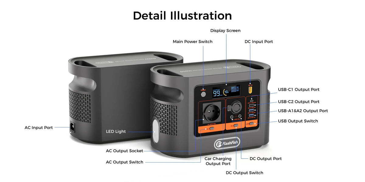
The authoritative E106B record lists 600W continuous pure-sine AC output and regional 110V or 230V variants. The E103 record lists AC charging from 100-240V up to 100W and a 230V regional AC output. On the supplied fields, an E106B regional unit could have ample continuous-output headroom for an E103 original charger whose demand remains within the documented 100W input ceiling.
That is only a paper screen. Confirm the delivered E106B voltage and frequency, the exact E103 charger input label, original cable, current manuals and both products' operating instructions. The records do not claim station-to-station compatibility or quantify the charger's real draw, transfer efficiency, charge time or usable energy.
Common mistakes to avoid
- Treating two battery capacities as though they can be added without transfer loss.
- Connecting independent AC outputs together or backfeeding a circuit.
- Using a barrel plug that fits without checking polarity and voltage.
- Ignoring the charger's input label because the station's battery is small.
- Running other donor loads without counting their simultaneous demand.
- Charging the recipient while it powers a high load without checking pass-through limits.
- Leaving a novel setup unattended or covered where heat cannot escape.
- Assuming a manufacturer-specific expansion feature works across models or brands.
A practical transfer checklist
- Write down donor model, regional AC output, frequency and continuous rating.
- Write down recipient model, original charger input and station charge-input ceiling.
- Confirm manufacturer instructions permit the intended connection and operating mode.
- Use intact approved cables; keep both stations dry, stable and ventilated.
- Disconnect non-essential donor and recipient loads for the first controlled test.
- Observe watts and temperature; stop on an error, unusual heat, smell, noise or damaged connection.
- Measure donor energy used and recipient energy gained only if the products expose suitable readings.
- End with a reserve and document the exact successful configuration.
The strongest alternative is often simpler: charge each station from an approved wall or solar source when available, then assign each station to a separate load. A station-to-station transfer makes sense only when moving energy has a clear operational benefit that outweighs the conversion loss.
FAQ
Can I plug one power station's charger into another power station?
Sometimes, if the donor output matches the recipient charger's voltage and frequency, the complete load stays within limits, and both manufacturers permit the arrangement. Exact manuals and regional labels govern.
Does charging one station from another increase total energy?
No. It moves part of the donor's stored energy into the recipient and loses some energy in conversion and station overhead.
Can I connect two AC outputs together?
No generic method is supported here. Never parallel or backfeed independent AC outputs unless the exact products provide a manufacturer-designed connection and instructions.
Is direct DC charging more efficient?
It may reduce conversion stages in a specifically supported design, but connector fit is not enough. Voltage, current, polarity, protocol and manufacturer permission must all match.
Do E106B and E103 have proven station-to-station compatibility?
No. Their published labels allow an on-paper AC screen for an E106B donor and E103 original charger, but no connection test or manufacturer compatibility statement is claimed.
Conclusion
One station may be able to run another station's original charger, but the arrangement should be treated as a lossy, model-specific energy transfer. It is not automatic capacity expansion and it never justifies joining independent outputs. Compare portable power station connection requirements before choosing a cable or charging path, then let the exact labels and manuals decide.
Sources and editorial notes
FlashFish product fields come from the authoritative local E103 and E106B manual-derived records with current Europe product status. EcoFlow and Jackery sources illustrate conversion and model-specific arrangements; they do not prove FlashFish compatibility. No connection was made, no efficiency was measured and no runtime, transfer percentage, cross-brand permission or automatic expansion result is claimed. Human review must verify regional labels, charger identity, manuals and the rendered article before publication.



Dejar un comentario
Este sitio está protegido por hCaptcha y se aplican la Política de privacidad de hCaptcha y los Términos del servicio.